Femtosecond Transient Absorption Spectroscopy
1. Overview The Femtosecond Laser Transient Absorption / Transient Fluorescence Spectroscopy System (TAS) is based on the pump-probe technique. By capturing the
Products
Sub-categories and products available in this range.
Description
Overview
1. Overview
The Femtosecond Laser Transient Absorption / Transient Fluorescence Spectroscopy System (TAS) is based on the pump-probe technique. By capturing the dynamic evolution of excited-state particles on ultrafast time scales (femtosecond to nanosecond), it reveals microscopic mechanisms in photophysics, photochemistry and materials science, and serves as an indispensable tool for studying light-matter interactions. Driven by a femtosecond laser and an optical delay line, the system provides femtosecond time resolution with broadband probing from UV to VIS and NIR, widely used in photocatalysis, perovskite solar cells, OLED, photovoltaic materials, photosynthesis and ultrafast dynamics research.
2. System Principle
(1) Transient absorption principle: The pump and probe pulses are separated in time - after the sample is excited by the pump pulse, the probe pulse interrogates the sample at different delay times. By comparing the probe absorption with and without excitation (ΔA), the dynamic evolution of excited states is captured. According to the Lambert-Beer law, ΔA can be expressed by transmission change; for ΔA<<1, ΔA≈−ΔT/ln10.
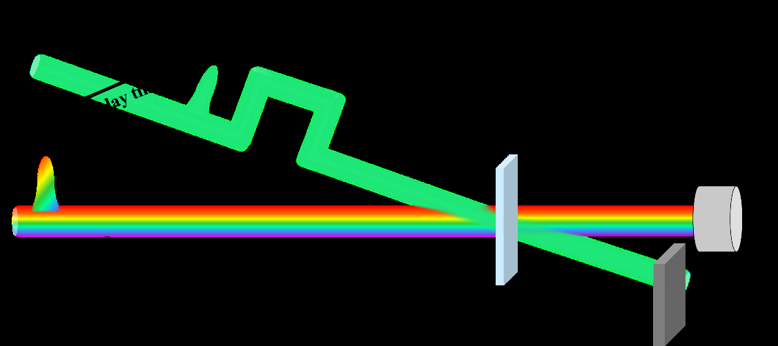
Fig.1 Transient absorption principle (pump-probe)
(2) Three signal sources: ①Ground state bleach (GSB) - excited-state population reduces ground-state absorption of the probe, giving a negative signal (ΔA<0); ②Excited state absorption (ESA) - excited electrons further absorb the probe to higher levels, giving a positive signal (ΔA>0); ③Stimulated emission (SE) - photons released in phase with the probe increase detected intensity, giving a negative signal. By recording spectra at successive delay times and extracting ΔA at a fixed wavelength, kinetic decay curves are obtained; fitting yields rate constants of different dynamic processes.
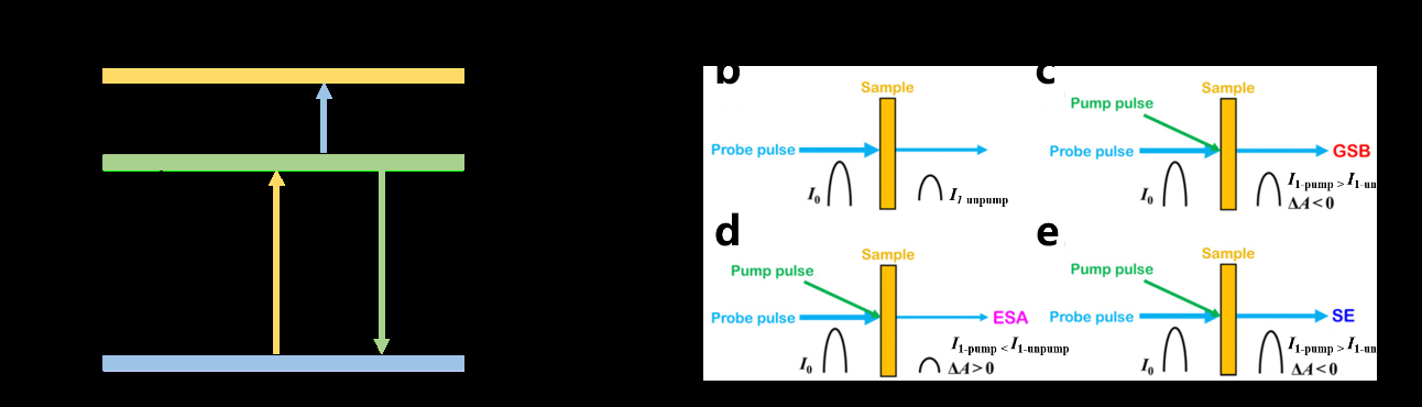
Fig.2 Signal sources (GSB/ESA/SE)
(3) Femtosecond time resolution: The time delay between pump and probe is Δt=Δx/c (Δx optical path difference, c speed of light); 1 μm path difference corresponds to ~3.3 fs. The optical delay line driven by stepper motor and precision ball screw provides micrometer-level displacement accuracy, ensuring stable femtosecond time-resolved measurements.
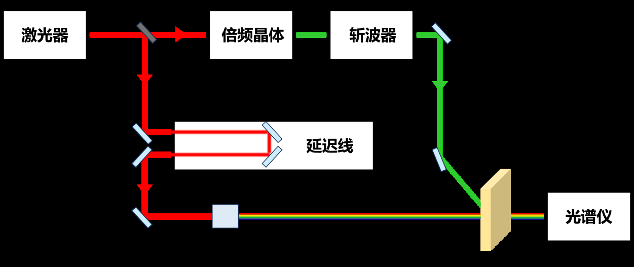
Fig.3 Basic optical path (pump-probe)
3. System Composition
The system consists of seven modules:
- Femtosecond laser: 1030 nm or 800 nm femtosecond laser (1 kHz or 5 kHz repetition, pulse width <120 fs, power <1 W @1kHz, TEM00);
- OPA / frequency-doubling module: generates pump wavelengths shorter or longer than fundamental (optional OPA, 266 nm femtosecond sum-frequency module);
- Pump external optical path: mirrors and beam risers delivering pump to the collection module;
- Probe external optical path: mirrors, beam expander and beam risers delivering laser to the main chamber;
- Main chamber: generates broadband probe white light (UV/VIS/NIR) and contains the optical delay line for the time window;
- Collection module: transmission/reflection dual-mode sample probing, fiber-coupled to spectrometer;
- Electrical control: industrial PC, timing control, spectrometer, chopper controller, delay-line controller, etc.
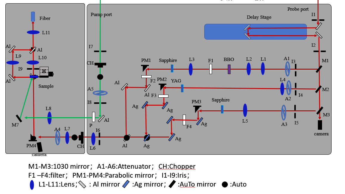
Fig.4 System composition and optical path
Probe white light covers three bands: UV 380~650 nm, VIS 480~950 nm and NIR 1100~1650 nm, generated by sapphire / CaF2 and YAG crystals respectively.
4. Key Specifications
| Parameter | Value |
|---|---|
| Time resolution | Determined by laser pulse width (<120 fs) |
| Time window | 0~2 ns (standard); 0~8 ns (option) |
| Probe wavelength | 450~800 nm (standard); 320~1600 nm (option, UV/VIS/NIR) |
| Laser source | Femtosecond 800 nm or 1030 nm (1 kHz or 5 kHz) |
| Pulse width | <120 fs |
| Laser power | <1 W (1 kHz) |
| Polarization | Linear / horizontal |
| Spatial mode | TEM00 |
| Probe bands | UV 380~650 nm; VIS 480~950 nm; NIR 1100~1650 nm |
| Signal modes | ΔA / ΔT/T / ΔR/R |
| Software | 2D color map, kinetics, spectrum, Time Zero calibration, delay-line auto-calibration, Overlap auto-alignment, sectional/exponential/file scan modes |
5. Typical Applications
- Photocatalysis: photogenerated carrier dynamics, charge separation and recombination;
- Perovskites & photovoltaics: carrier mobility, trap states and ultrafast dynamics;
- OLED & luminescent materials: excited-state lifetimes, triplet-triplet annihilation, upconversion;
- Photosynthesis & bio-photochemistry: energy transfer and charge transfer in photosynthetic pigments;
- Ultrafast photophysics: excited-state absorption, stimulated emission, ground-state bleach, Stokes shift, internal conversion;
- Materials science: carrier dynamics of semiconductors, quantum dots, 2D materials (graphene / TMDs).
6. Software & Data Acquisition
The system is equipped with an integrated control and data-acquisition platform (UTAS / degenerate TA software): 2D color map acquisition, kinetics extraction, spectrum display; sectional / exponential / equal-exponential / file-based delay scan modes; Time Zero interface (delay-line auto-calibration, chopper phase adjustment, background deduction, Overlap auto-alignment); ΔA / ΔT/T / ΔR/R mode switching, reference and gain control; automatic data saving with CSV export for Origin and other tools.
7. Service & Support
Sunpump Opto-Electronic provides full-service support covering requirement analysis, system integration, installation and commissioning, operator training and after-sales support. Custom functions are available on request (e.g., Pump-Pump-Probe, additional absorption spectroscopy, absolute photoluminescence quantum yield, transient reflection, confocal microscopy).
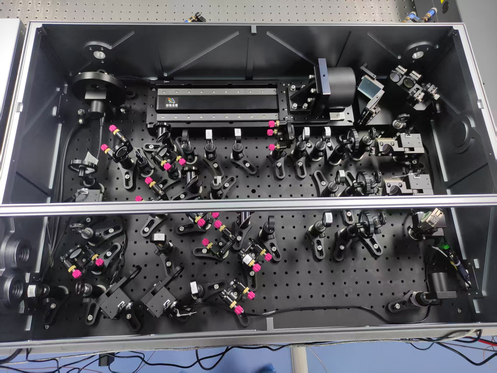
Fig.5 System optical path (actual setup)
1. Overview
The Femtosecond Laser Transient Absorption / Transient Fluorescence Spectroscopy System (TAS) is based on the pump-probe technique. By capturing the dynamic evolution of excited-state particles on ultrafast time scales (femtosecond to nanosecond), it reveals microscopic mechanisms in photophysics, photochemistry and materials science, and serves as an indispensable tool for studying light-matter interactions. Driven by a femtosecond laser and an optical delay line, the system provides femtosecond time resolution with broadband probing from UV to VIS and NIR, widely used in photocatalysis, perovskite solar cells, OLED, photovoltaic materials, photosynthesis and ultrafast dynamics research.
2. System Principle
(1) Transient absorption principle: The pump and probe pulses are separated in time - after the sample is excited by the pump pulse, the probe pulse interrogates the sample at different delay times. By comparing the probe absorption with and without excitation (ΔA), the dynamic evolution of excited states is captured. According to the Lambert-Beer law, ΔA can be expressed by transmission change; for ΔA<<1, ΔA≈−ΔT/ln10.
Fig.1 Transient absorption principle (pump-probe)
(2) Three signal sources: ①Ground state bleach (GSB) - excited-state population reduces ground-state absorption of the probe, giving a negative signal (ΔA<0); ②Excited state absorption (ESA) - excited electrons further absorb the probe to higher levels, giving a positive signal (ΔA>0); ③Stimulated emission (SE) - photons released in phase with the probe increase detected intensity, giving a negative signal. By recording spectra at successive delay times and extracting ΔA at a fixed wavelength, kinetic decay curves are obtained; fitting yields rate constants of different dynamic processes.
Fig.2 Signal sources (GSB/ESA/SE)
(3) Femtosecond time resolution: The time delay between pump and probe is Δt=Δx/c (Δx optical path difference, c speed of light); 1 μm path difference corresponds to ~3.3 fs. The optical delay line driven by stepper motor and precision ball screw provides micrometer-level displacement accuracy, ensuring stable femtosecond time-resolved measurements.
Fig.3 Basic optical path (pump-probe)
3. System Composition
The system consists of seven modules:
- Femtosecond laser: 1030 nm or 800 nm femtosecond laser (1 kHz or 5 kHz repetition, pulse width <120 fs, power <1 W @1kHz, TEM00);
- OPA / frequency-doubling module: generates pump wavelengths shorter or longer than fundamental (optional OPA, 266 nm femtosecond sum-frequency module);
- Pump external optical path: mirrors and beam risers delivering pump to the collection module;
- Probe external optical path: mirrors, beam expander and beam risers delivering laser to the main chamber;
- Main chamber: generates broadband probe white light (UV/VIS/NIR) and contains the optical delay line for the time window;
- Collection module: transmission/reflection dual-mode sample probing, fiber-coupled to spectrometer;
- Electrical control: industrial PC, timing control, spectrometer, chopper controller, delay-line controller, etc.
Fig.4 System composition and optical path
Probe white light covers three bands: UV 380~650 nm, VIS 480~950 nm and NIR 1100~1650 nm, generated by sapphire / CaF2 and YAG crystals respectively.
4. Key Specifications
| Parameter | Value |
|---|---|
| Time resolution | Determined by laser pulse width (<120 fs) |
| Time window | 0~2 ns (standard); 0~8 ns (option) |
| Probe wavelength | 450~800 nm (standard); 320~1600 nm (option, UV/VIS/NIR) |
| Laser source | Femtosecond 800 nm or 1030 nm (1 kHz or 5 kHz) |
| Pulse width | <120 fs |
| Laser power | <1 W (1 kHz) |
| Polarization | Linear / horizontal |
| Spatial mode | TEM00 |
| Probe bands | UV 380~650 nm; VIS 480~950 nm; NIR 1100~1650 nm |
| Signal modes | ΔA / ΔT/T / ΔR/R |
| Software | 2D color map, kinetics, spectrum, Time Zero calibration, delay-line auto-calibration, Overlap auto-alignment, sectional/exponential/file scan modes |
5. Typical Applications
- Photocatalysis: photogenerated carrier dynamics, charge separation and recombination;
- Perovskites & photovoltaics: carrier mobility, trap states and ultrafast dynamics;
- OLED & luminescent materials: excited-state lifetimes, triplet-triplet annihilation, upconversion;
- Photosynthesis & bio-photochemistry: energy transfer and charge transfer in photosynthetic pigments;
- Ultrafast photophysics: excited-state absorption, stimulated emission, ground-state bleach, Stokes shift, internal conversion;
- Materials science: carrier dynamics of semiconductors, quantum dots, 2D materials (graphene / TMDs).
6. Software & Data Acquisition
The system is equipped with an integrated control and data-acquisition platform (UTAS / degenerate TA software): 2D color map acquisition, kinetics extraction, spectrum display; sectional / exponential / equal-exponential / file-based delay scan modes; Time Zero interface (delay-line auto-calibration, chopper phase adjustment, background deduction, Overlap auto-alignment); ΔA / ΔT/T / ΔR/R mode switching, reference and gain control; automatic data saving with CSV export for Origin and other tools.
7. Service & Support
Sunpump Opto-Electronic provides full-service support covering requirement analysis, system integration, installation and commissioning, operator training and after-sales support. Custom functions are available on request (e.g., Pump-Pump-Probe, additional absorption spectroscopy, absolute photoluminescence quantum yield, transient reflection, confocal microscopy).
Fig.5 System optical path (actual setup)
Features
- [{"nameEn": "Femtosecond time resolution"}, {"nameEn": "Broadband probe (UV/VIS/NIR)"}, {"nameEn": "Transient absorption / fluorescence"}]